
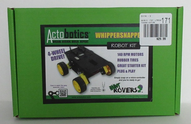
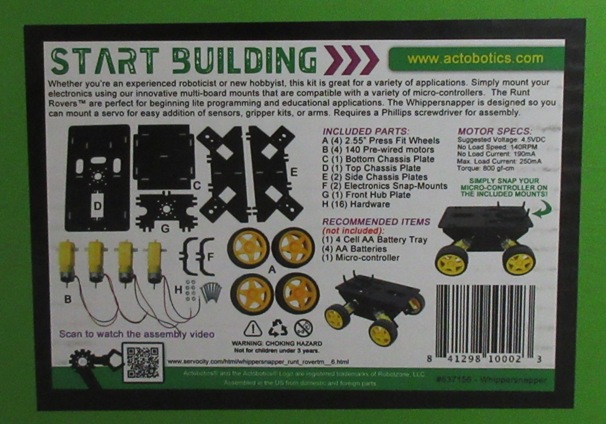
Chassis is the Wippersnapper Runt Rover. Easy to assemble with just eight screws to hold the motors and the rest is snap together.
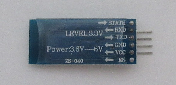
Used an HiLetgo HC-06 RS232 Wireless Serial Bluetooth to add remote control. Avoid using the newer BLE bluetooth 4.0 modules, there is less support for these devices in the android app market.
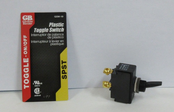
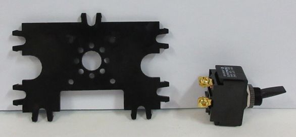
A simple toggle switch to help preserve battery life.
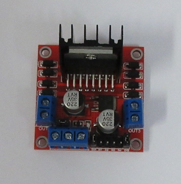
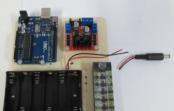
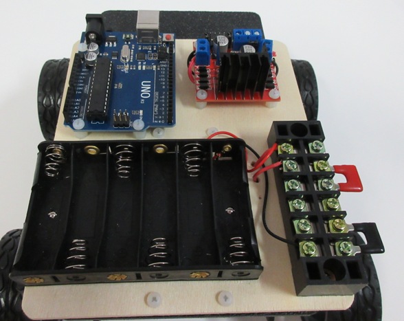
Qunqi L298N Motor Drive Controller Board Module Dual H Bridge DC Stepper for Arduino.
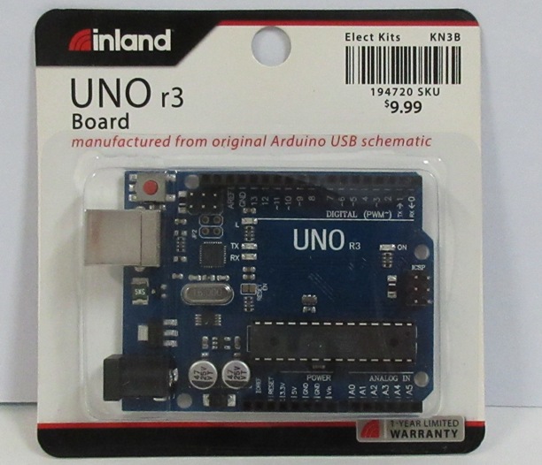
A medium priced UNO R3 board to control the car.
Nylon standoffs size M3, not as strong as metal standoffs, but less chance of shorting out modules with crowded circuitry. I used black quarter inch spacers between the chasis and the board and white spacers between the board and the components. Note for one of Arduino mounting holes the hole was too close to the header so I had to use a M2.5 spacer.

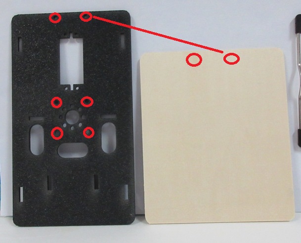
A 6x5 inch craft board very esy to make holes on with just screw drivers

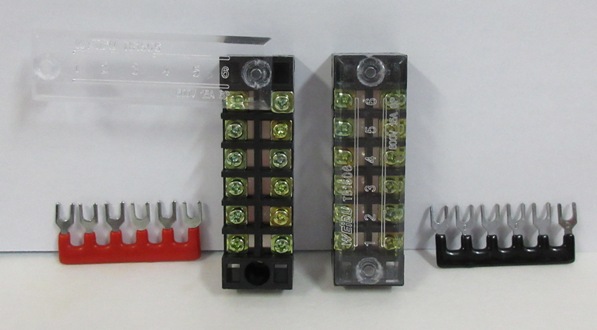
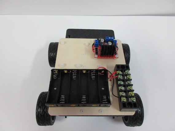
Hilitchi 6 Position Double Row Screw Terminal Strip. Useful for joining mltiple wires to Vin and ground.
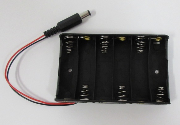
6 AA Battery Holder 9V Output by Corpco. The motors are rated at 6 volts but both the Arduino and Motor controller can handle much more so I picked a 9v battery pack and in software will limit the power going to the motors.
Use the top panel of the chasis as a templete for making mounting holes in the wood board.
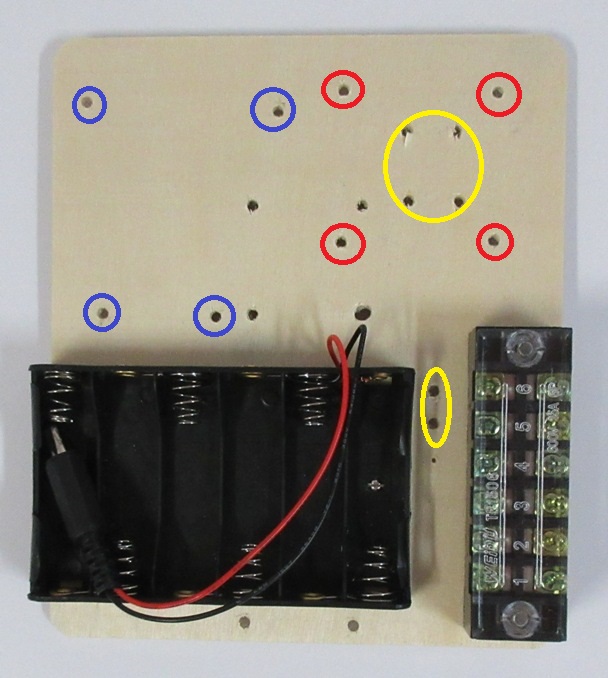
Use the Arduino as a template for the holes in blue, the motor controller for those in red, and the holes in yellow are for wires so they don't need to be exact. The battery pack and terminals are screwed directly to the board so they should be done first as they will be hard to get to once the board is attached to the chasis.
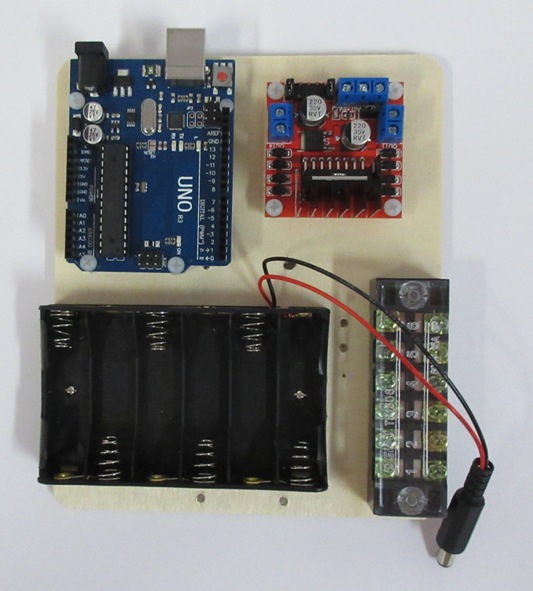
Once the holes are made attach the white spacers to the board, I also mounted the Arduino and motor controller to check they fit well. That is when I found I needed to replace the spacer near the Arduino button with a smaller size.
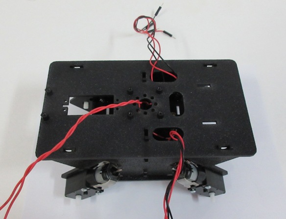
Mount the black spacers on the top of the chassis , it is easier to do now before the chasis is asembled.
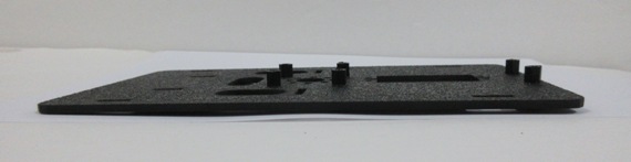
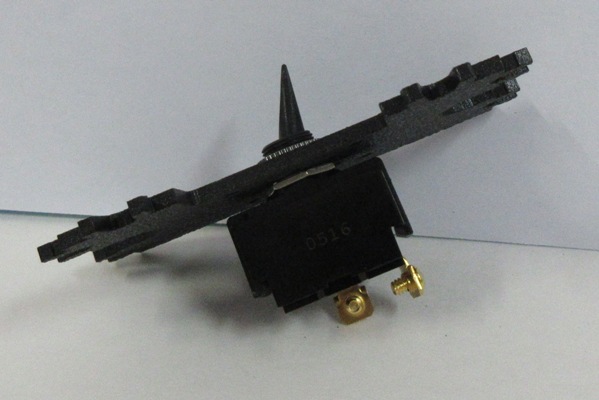
Also mount the switch to the part that hold the two sides of the chasis together so that it flips on/off from side to side.
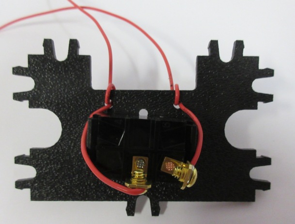
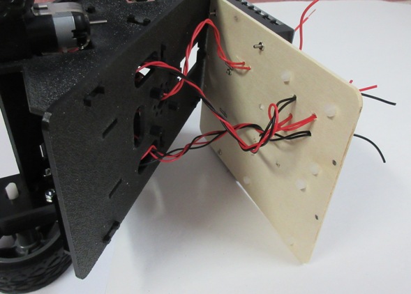
Next add the wires to the switch. I looped them around the two holes in the plate prevent them from getting pulled of the switch.
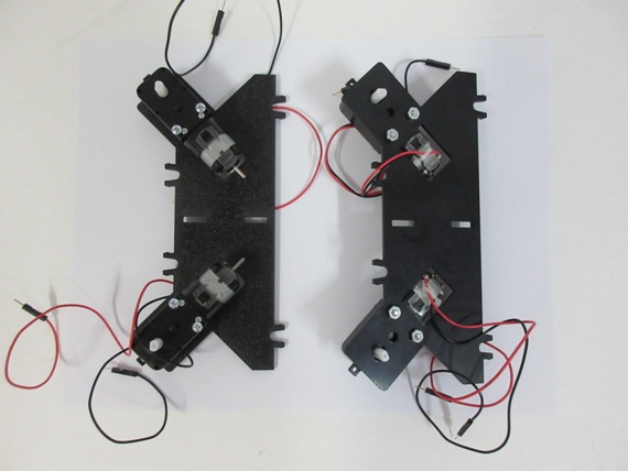
Then mount the motors on the sides of the chasis. The chasis panels come with a textured side and a smooth side, I liked the textured surface to be seen so I mounted the motors on the textured side.
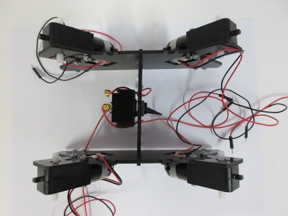
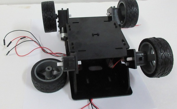
Connect the two sides of the chasis with the center panel. Note the longer side with the single tab will later attach to the bottom of the car, and the oposite side with two tabs will attach the the top board of the chassis.
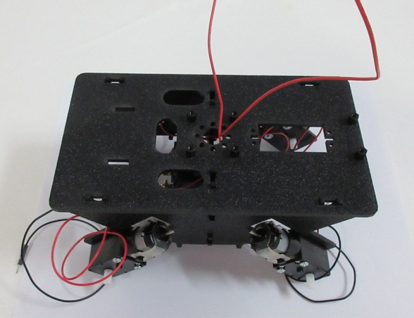
Mount the top pannel of the chasis, with having first brought up the wires for the switch.
Mount the bottom of the chasis.
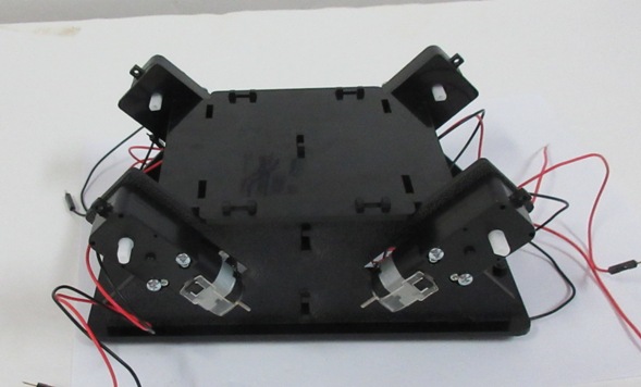
Bring out the wires from the motors keeping each side of the car seperate.
Attach the wheels.
And trim off the male connectors at the end of the wires, this way they are easier to pass through the board and also take up less space when mounted to the motor controller.
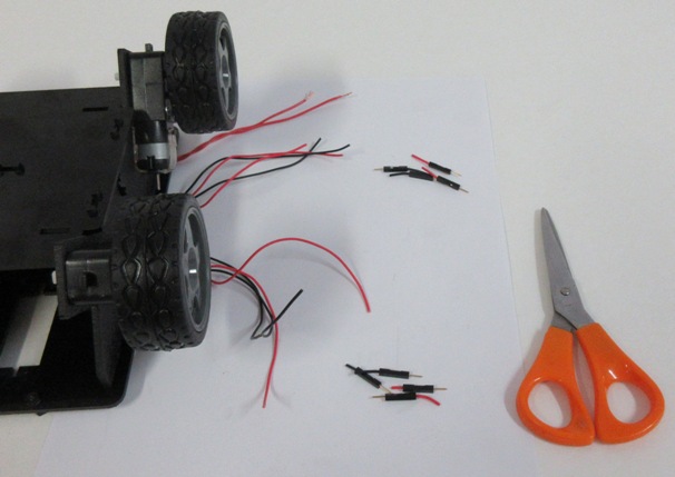
Trim off the connector at the end of the battery pack wires, as the leads will go directly to the terminal strip.
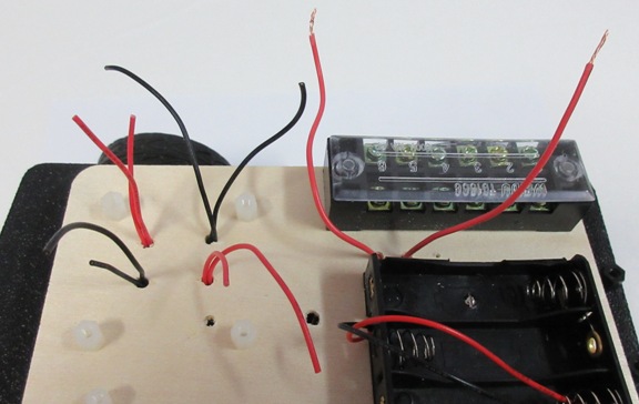
Twist the wires for each set (Switch, Left Motors, Rigth Motors) so they can neetly be hidden between the top of the chasis and the wood board. The switch wires then come up through the holes near the power strip. The motor wires come up below the motor controller as a pair of red and a pair of black kepping to their side of the car.
On each side of the controler connect the red wires for that side to one connector and black wires to the second. Note the order of the red or black are not important as once the car is running any issue with the diection of the car can be corrected in the placing of the wires on the Arduino.
Connect the red wire from the battery pack and one of the switch wires to the first terminal closest to the motor controller. Then connect the other end of the switch to the second terminal, this will be the Vin supply to the Arduino and motor controller.
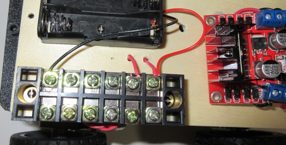
Secure the motor controller to the board and pack the wires neatly between the board and the top of the chasis so that the six screws can secure the board to the chasis. Then connect the black wire from the battery pack to the last terminal on the strip. This will be ground for all components.
Bridge the second and third terminals as several components will need Vin. Bridge the fifth and sixth terminals as several components will need ground. Keep the fourth terminal free in case 5 volts needs to be distributed. In this setup only the bluetooth needed 5 volts and ground, which it was able to get from the Arudino directly. The Arduino can now be secured to the board.
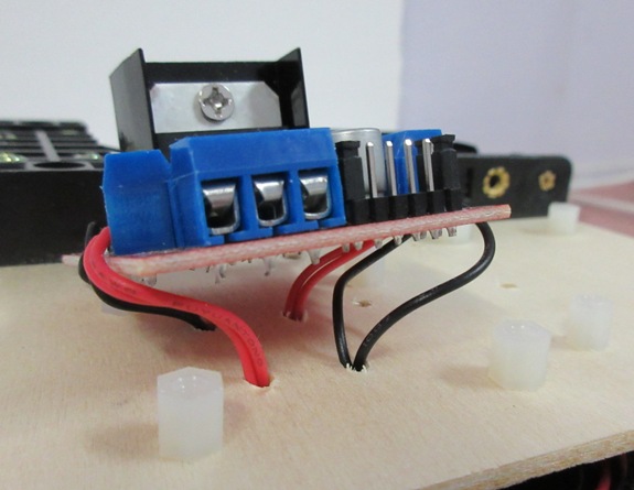
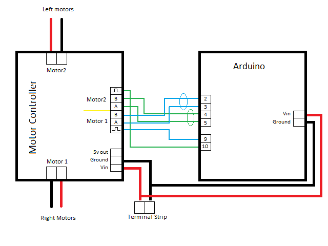
Connect Vin and ground to the motor controller and the Arduino. Then connect the six input wires for motor control to the Ardino. The motor enable inputs are pulse width signals that control the motor speed. Motor 1 enable goes to pin 9 of the arduino and Motor 2 enable goes to pin 10. The other four input pins control the direction of the motors a pair for each motor. As you change which wire of the pair is set high the motor changes direction. Motor 1 input pair goes to pins 2 and 3 of the Arduino. Motor 2 input pair goes to pins 4 and 5. If you notice the motor is not going in the correct direction you can swap the two wires in the pair for that motor on the Arduino.
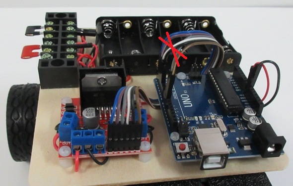
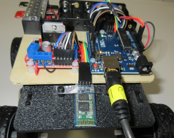
Note after these photos were taken I found the wires shown in photo below were not set up properly and had to be rearanged on the Arduino.
The Bluetooth receiver connects directly to the Arduino for TX, RX, 5v and ground. I added a small strip of clear plastic to hold the Bluetooth in place.
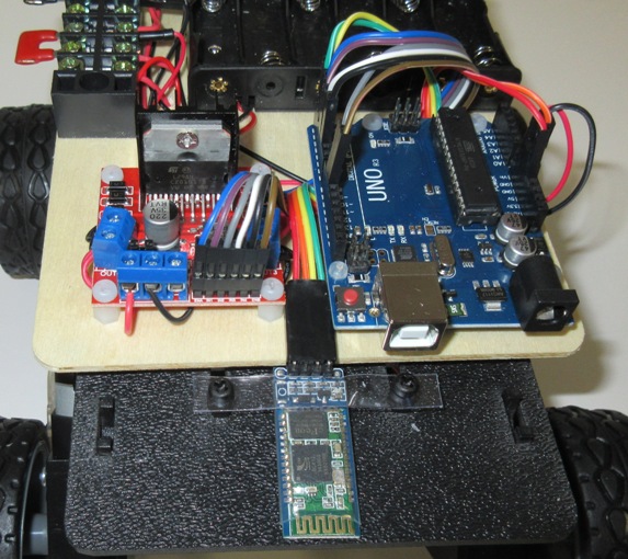
Before adding the batteries I attached the Arduino to the PC to download the latest copy of the C program used to control the car. Note I had to disconnect the bluetooth from RX and TX while using the USB connection.
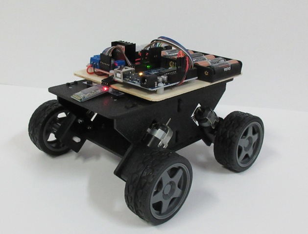
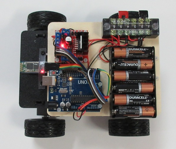
Top view with the Bluetooth reconnected and the batteries installed.
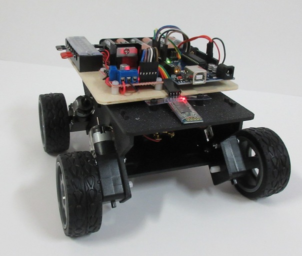
Side view
There are quite a few android apps avaiable for controlling projects via bluetooth. I used Bluetooth Electronics by Keuwlsoft. It allows you to assign ASCII characters to buttons which get sent to the Aruino when the buttons are pressed. Also has other UI elements like switches and meters.